Bodine Gtd20 Wiring Diagram
(1) transfer a lighting load from normal power to generator or central. Bodine, generator transfer device, fluorescent, incandescent, led bulb type, 2 15/16 in length item # 32wx18;

31 Bodine Emergency Ballast Wiring Diagram Wiring Diagram Database
Your email address will not be published.

Bodine gtd20 wiring diagram. (on t2) and a 12 awg pigtail going to 3 (on t1). Not all of bodine's stuff is listed for use in an emergency system. The gtd20a senses the loss of normal power and, in response, switches the lighting load to a designated alternate power source.
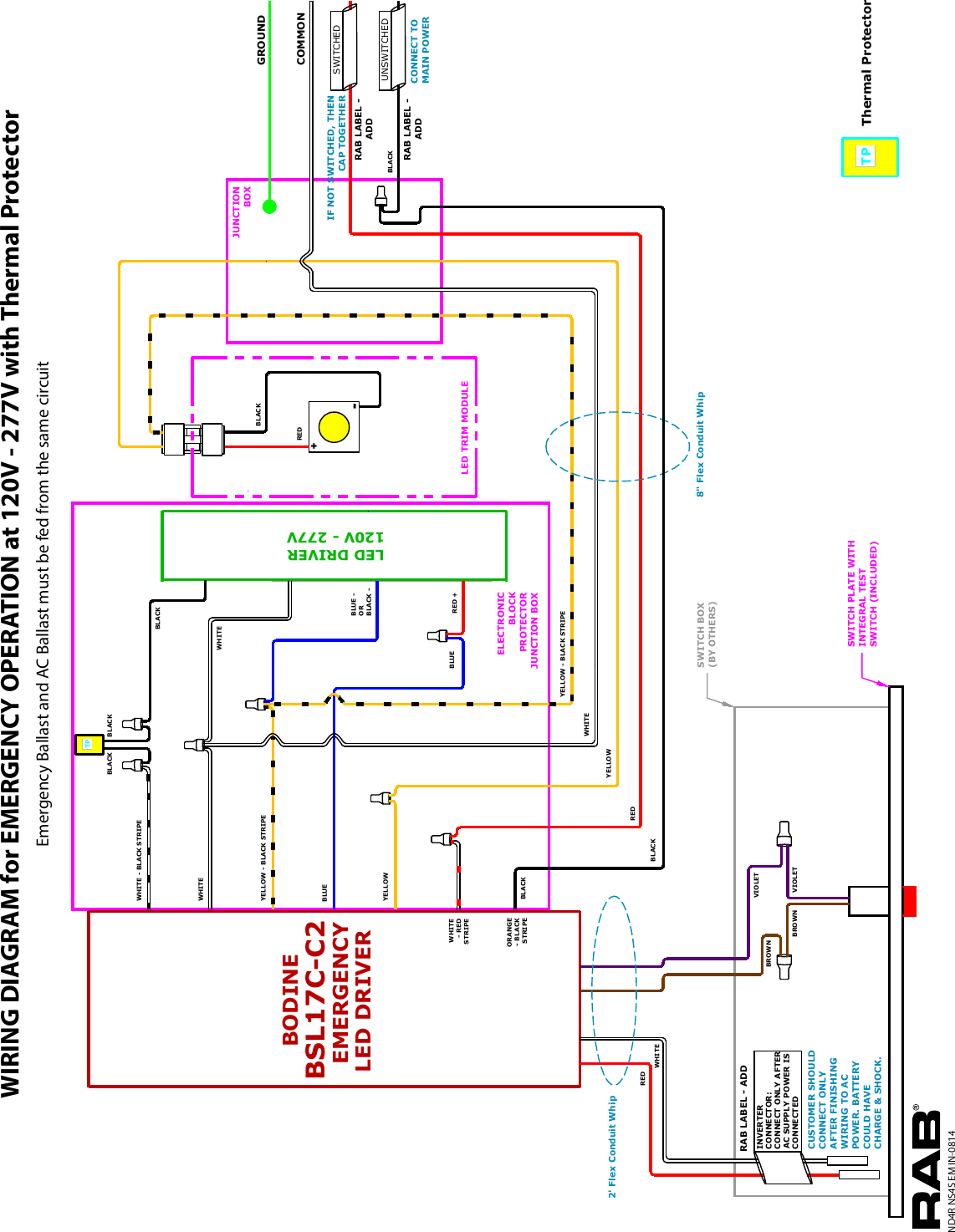
> select the appropriate wiring diagram on back to connect the emergency ballast to the ac ballast and lamp(s). Wiring diagrams multiple receptacle outlets home electrical wiring diy electrical outlet wiring. For generator or central inverter supplied lighting.
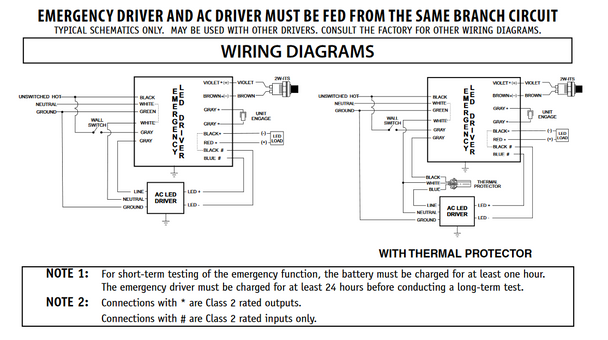
Wiring diagrams for 2 lamp emergency operation 2 4 17 40 w lamps only wiring diagram for 1 lamp emergency operation emergency ballast and ac ballast must be fed from the same branch circuit typical schematics only. > follow the corresponding wiring diagram to connect the remaining leads. > after installation is complete, supply ac power to the.
The gtd20a works in conjunction with an auxiliary generator or central inverter system to power designated lighting loads up to 20 amps regardless of local switch position. The device can be used to: Com bodine b50 wiring diagram product support bodine electric.
Ing diagrams by matching the violet and brown leads and connecting the black leads to the emergency ballast. The device shall be capable of bypassing the local switching means when normal utility power has been lost. Operation the gtd20a senses the loss of normal power and switches the lighting load, connecting it to a an emergency lighting circuit.
Wiring diagrams are available at: Neutral is also according to diagram. When you order the gtd20 bodine relay control device, we will substitute with equivalent or better product.
To verify that this is the correct wiring diagram for your bodine product, please check for the connection diagram reference number in the specifications table on the applicable item/model page. Use the proper wiring diagram in the appropriate section of these instructions. Wire gauges for all leads terminating at t2 should.
Name * email * website. The gtd20a senses the loss of Certifications, wiring, builds, scales, reviews, accessories, classifieds, and more!
The gtd20 is listed only. Connection diagram for 230 460vac 9 wire reversible 3 phase gearmotors and motors 07410012. The gtd20 works with an auxiliary inverter system to power switchable loads up to 20 amps, regardless of local light switch position (on/off).
Click download pdf to view this wiring diagram. An unswitched, normal ac power source (120 through 277 vac, 50/60 hz) and a direct, separate connection to a > refer to the illustrations on the following pages for proper wiring connections and choose the correct illustration for your application.
Leave a reply cancel reply. Country of origin is subject to change. The device senses the loss of normal power, bypasses the
E m e r g. Jumpers from 1 on t1 to 4 on t2 is made as well as 5 on t1 to 4 on t2.suggestions? Extension cords should not be used.
Emergency lighting for field installation; Or a switch bypass under ul 924. Jumper connections on t1 and t2 are contractor installed.
The gtd20a is suitable for use in indoor and damp locations. Required fields are marked * comment. For additional applications and information, contact the factory.
I have a question regarding the philips bodine gtd20a. The device shall consist of relay switching circuitry, a test switch, a normal power indicator light and an alternate power indicator light Allows the user a wide variety of wiring options.
> remove gtd20a lid and install necessary conduit and wiring (not supplied) to the gtd20a. Ul listed for us and canada under ul 924 ul listed for the us under ul 1008 Bodine gtd20 the gtd20 switch bypass device offers energy saving technology for central inverter system supplied emergency lighting.
Use the proper wiring diagram in the appropriate section of these instructions. Lighting loads equipped with a philips bodine gtd20a lighting relay control device.
Bodine Emergency Ballast Wiring Diagram

39 Dayton Drum Switch Wiring Diagram Wiring Diagram Online Source

30 Bodine Motor Wiring Diagram Wiring Diagram Database

Bodine B90 Emergency Ballast Wiring Diagram Wiring Diagram and Schematic

Philips Bodine B50 Wiring Diagram For Your Needs

Wiring Diagram For Philips Bodine Elis100

Bodine GTD Jademar Lighting

Philips Bodine B50 Wiring Diagram

Philips Bodine GTD Generator Transfer Device for Emergency Lighting

Bodine Emergency Ballast Wiring Diagram Drivenheisenberg

31 Bodine Emergency Ballast Wiring Diagram Wiring Diagram Database

Emergency Ballast Wiring Diagram Wiring Diagram & Schemas

10100 Bodine Emergency Ballast Wiring Diagram Wiring Diagram Schema
Bodine Emergency Ballast Wiring Diagram Wiring Diagram

Bodine Emergency Ballast Wiring Diagram Drivenheisenberg
Bodine Led Wiring Diagram Wiring Diagram Schema
Philips Bodine BSL10LST Coldpak Compact LED Emergency Driver

WeilMcClain boiler wont kick on Community Forums
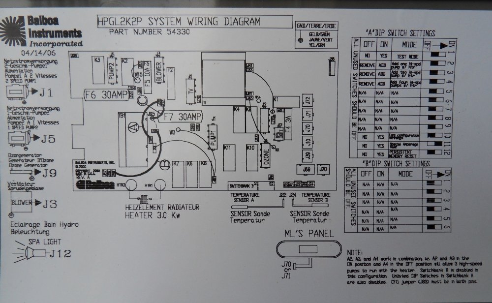
ERROR CODE cfe j82 hydropool balboa M7 GL2000 Portable Hot Tubs & Spas Pool and Spa Forum